 Help
Help
|
Bilbao Crystallographic Server
Help
|
Each table consists of two main parts. The first two columns under the heading ’k-vector description’ refer to the description of k-vectors found in Tables 3.9 and 3.11 of CDML [2]. It consists of labels of k-vectors (Column 1) and their parameter descriptions (Column 2). (Note that CDML substitute the Greek-character labels for the symmetry points and lines inside the Brillouin zone by a symbol consisting of two Roman characters, e. g. GM for Γ, LD for Λ, etc.) No ranges for the parameters are listed in CDML. Apart from the labels of points, lines and planes of CDML which are retained in the listings of the Brillouin-zone database, many new names have been given to points and lines which are not listed in CDML. In such cases, lines equivalent, for example, to a line H or the end points of a line H, as well as points equivalent to a point H may also be designated by the letter H but distinguished by indices. In order to recognize points and lines easily, the indices of points are always even: H0, H2, H4; those of lines are always odd: H1, H3. The new k-vectors are equivalent to those of CDML and are necessary to enable the uni-arm description of the k-vector types. The sign ’∼’ relates equivalent k-vectors, see e. g. the lines S ∼ S1 = [HL0] in the table and the figure of the space group P321 (No. 150), or the line P ∼ P1 = [P0T] and the point T ∼ T2 in the tables and figures of the space group R3 (No. 146).
Different k-vectors with the same CDML label always belong to the same k-vector type, i. e. they correspond to the same Wyckoff position. k-vectors with different CDML labels may either belong to the same or to different types of k-vectors. When k-vectors with different CDML labels belong to the same k-type, the corresponding parameter descriptions are followed by the letters ’ex’. Symmetry points, lines of symmetry or planes of CDML, related to the same Wyckoff position, are grouped together in a block. In the k-vector tables, neighbouring Wyckoff-position blocks are distinguished by a slight difference in the background colour. For example, the k-vectors of R3 are distributed in two k-vector types:
The parameter description of a region may be described by the vertices of that region in brackets [. . . ]. One character in brackets, e. g. [P], means the point P. Two points within the brackets, e. g. [A B] means the line from A to B. Three points within the brackets, e. g. [A B C] means the triangular region of a plane with the vertices A, B and C. Four or more points may mean a region of a plane or a threedimensional body, depending on the positions of the points. The meaning can be recognized by studying the corresponding figure. Commas between the points, e. g. [A, B, C] indicate the set {A, B, C} of the three points A, B, and C.
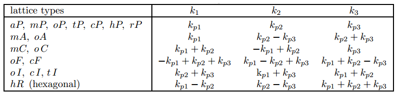
The wave-vector coefficients of CDML (Column 2 of the k-vector tables) refer always to a primitive basis irrespective whether the conventional description of the space group in ITA is with respect to a centred or primitive basis. For that reason, for space groups with centred lattices, the wave-vector coefficients with respect to the usual conventional reciprocal basis, i. e. dual to the conventional centred basis in direct space of ITA, are also listed in the column under the heading ’Conventional basis’ of the k-vector tables. The relations between the ’conventional’ and ’primitive’ coefficients of the wave vectors are summarized in the following table:
The data for the crystallographic classification scheme of the wave vectors are listed under the heading ’ITA description’ of the k-vector tables. The columns ’Wyckoff positions’ show the data of ’multiplicity’, ’Wyckoff letter’ and ’site symmetry’ of the Wyckoff positions of the symmorphic space group G0 of ITA which is isomorphic to the reciprocal-space group (G)*. The multiplicity of a Wyckoff position divided by the number of lattice points in the conventional unit cell of ITA equals the number of arms of the star of the k-vector of the Wyckoff-position block. The alphabetical sequence of the Wyckoff positions determines the sequence of the CDML labels. The tables start with the Wyckoff letter a for the Wyckoff position of the highest site symmetry and proceeds in alphabetical order until the General Position (GP) is reached. ’Oriented’ point-group symbols are used to indicate the site-symmetry groups which coincide with the little co-groups of the wave vectors (for ’oriented’ point-group symbols cf. ITA, Section 2.2.12). The parameter description of the Wyckoff position of G0 is shown in the last column of the wave-vector tables. Algebraic statements are used for the description of the parameter ranges. According to the ITA description, the line DT of P321 corresponds to the Wyckoff position 2g with a site-symmetry group 3... Its parameter description 0, 0, z : 0 < z < 1/2 indicates that the independent segment of the line 0, 0, z is limited by the special k-vector points Γ (z = 0) and A (z = 1/2) with z varying between 0 and 1/2. In some cases, the algebraic expressions are substituted by the designation of the parameter region in order to avoid clumsy notation. The parameter descriptions of the flagpoles and the wings are shown under the k-vector tables.
Due to the dependence of the shape of the Brillouin zone on the lattice-parameters relations there may be vertices of the Brillouin zone with a variable coordinate. If such a point is displayed and designated in the tables and figures by an upper-case letter, then the label of its variable coefficient used in the parameter-range descriptions is the same letter but lower case. Thus, the variable coefficient of the point G0 is g0, of LD0 is ld0, etc. (cf. table of space group R3).
As already indicated, the parameter ranges are chosen such that each orbit of the Wyckoff position of ITA, i. e. also each k-vector orbit, is listed exactly once. As a result, one usually gets rather complicated descriptions of the independent parameter regions included in the General-position block. For example, the statement found in the table of space group P321 (No. 150):
| GP | u,v,w | 6 | l | 1 | x, y, z: -x < y < x/2, 2x-1 <y, -1/2 < z ≤ 1/2 U |
| U x, -x, z : 0 < x < 1/3, 0 < z <1/2 U | |||||
| U x, x/2, z : 0 < x < 2/3, 0 < z <1/2 U | |||||
| U x, 2x-1, z : 1/3 < x < 2/3, 0 < z <1/2 |
At the bottom of the web page with the k-vector table one finds an auxiliary tool which allows the complete characterization of any wave vector of the reciprocal space (not restricted to the first Brillouin zone): given the k-vector coefficients referred either to a primitive (CDML) or to a conventional basis, the program assigns the k-vector to the corresponding wave-vector symmetry type, specifies its CDML label, calculates the little co-group and the arms of the k-vector stars. Consider, for example, a k-vector with coefficients (0.4, 1.3, 0) of the space group P321 (No. 150). It is a vector outside the Brillouin zone and its coefficients do not correspond to any of the parameter descriptions of the k-vector representatives listed in the table of the space group P321 (No. 150). The output of the auxiliary tool indicates that k (0.4, 1.3, 0) is a point of a special k-vector line of type LD and belongs to the Wyckoff-position block 3j. Its star consists of three k-vectors, k* = {(0.4, 1.3, 0),(1.3, -1.7, 0),(-1.7, 0.4, 0)}. The little co-group ..2 is generated by a two-fold rotation that can be identified by direct inspection among the symmetry operations of (P312)* as 2 x,0,0 (x-y, -y, -z).
|
Bilbao Crystallographic Server www.cryst.ehu.es |
For comments, please mail to administrador.bcs@ehu.es |